Clounagh Technology and Design
Year - 9 USB Mood Light Project.
In this page you will find all the information you need to complete the Mini Light project.
-
In this section the components are soldered onto the pre-drilled PCB board.
-
The photos below you can see the circuit before any components were inserted or soldered onto it.
-
This side of the board has tracks of wire etched on to it and they conduct the current around the circuit.
-
In the photos below you can see the circuit at various stages of manufacture.
-
In order to make the battery clip secure, the red and black wires are fed through a hole before being soldered. This means that the battery clip should not pull out easily.
For this circuit to work you need to input a number of different components.
-
1x LED
-
1x Resistor
-
1x Switch
-
1x USB Power supply lead
Images for the circuit components and their symbols are shown below.
Tools required to build a circuit
Below are images, names and descriptions of the tools needed to manufacture a circuit.
Manufacturing The Housing
The housing for the Mini Light project is designed to hold the circuit. It was made from 1 piece of acrylic and a square of Norway Spruce wood.
-
To begin, the edges of the acrylic was cleaned using wet and dry sand paper. Once the edges were free from scratches the polisher was used to buff the edges to a nice smooth finish.
-
A template was then used to mark out the positions of the holes. A cordless drill was then used to drill a hole in each location.
-
The line bender was then used along with 2 bending jigs to bend the housing to shape.
-
The piece of Norway Spruce was then cut in half making two triangles. They were then stuck together using double sided tape.
-
The pieces of Norway Spruce were then sanded so they were the same shape/size.
-
The housing was then assembled and the circuit was inserted into the housing to complete.
See images below
 Blank Circuit BoardThis is the circuit board before any components were added. |  Circuit with componentsThe components were added to the circuit board. Remember some components need to be inserted a particular way to work properly! |  Soldered CircuitThis is an image of the circuit with each of the components soldered in place. |
|---|
 Resistor Circuit Symbol | 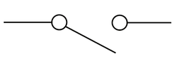 Switch Circuit Symbol |  LED Circuit Symbol |
|---|---|---|
 USB Power Lead |
 Soldering IronThis is a soldering iron. It is used to melt solder wire and help make an electrical connection within a circuit. (You can read more about soldering by clicking the button below.) |  Wire StrippersWire strippers are used to remove the plastic coating and expose the metal wire so it can be soldered to components/circuits. |  Long Nose PliersThese pliers are used for both cutting and gripping wires. Their namesake long gripping nose provides excellent control and reach for fine work in small or crowded electrical enclosures. |
|---|---|---|
 Side CuttersThese pliers are used to cut the wire to the correct length. |


